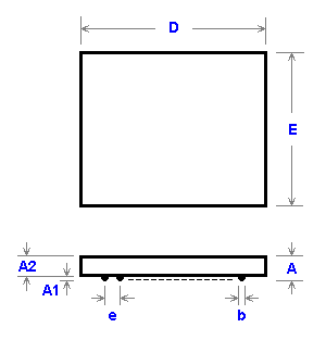
|
NAME
|
SYMBOL |
MIN |
NOM |
MAX |
|
Profile
|
A |
- |
- |
1 |
|
Ball Height
|
A1 |
0.17 |
0.22 |
0.27 |
|
Body Thickness
|
A2 |
0.61 |
0.66 |
0.71 |
|
Ball Diameter
|
b |
0.25 |
0.3 |
0.35 |
|
Body Size
|
D |
15.93 |
16 |
16.07 |
|
Body Size
|
E |
11.93 |
12 |
12.07 |
|
Ball Pitch
|
e |
- |
0,5 |
- |
|
Ball Array D
|
GD |
- |
28 |
- |
|
Ball Array E
|
GE |
- |
14 |
- |
|
|
NAME
|
SYMBOL |
MIN |
NOM |
MAX |
|
Profile
|
A |
0.8 |
0.9 |
1 |
|
Ball Height
|
A1 |
0.15 |
0.2 |
0.25 |
|
Body Thickness
|
A2 |
- |
- |
- |
|
Ball Diameter
|
b |
0.27 |
0.32 |
0.37 |
|
Body Size
|
D |
15.9 |
16 |
16.1 |
|
Body Size
|
E |
11.9 |
12 |
12.1 |
|
Ball Pitch
|
e |
- |
0,5 |
- |
|
Ball Array D
|
GD |
- |
28 |
- |
|
Ball Array E
|
GE |
- |
14 |
- |
|
|
NAME
|
SYMBOL |
MIN |
NOM |
MAX |
|
Profile
|
A |
0.8 |
0.9 |
1 |
|
Ball Height
|
A1 |
0.17 |
0.22 |
0.27 |
|
Body Thickness
|
A2 |
- |
- |
- |
|
Ball Diameter
|
b |
0.25 |
0.3 |
0.35 |
|
Body Size
|
D |
15.9 |
16 |
16.1 |
|
Body Size
|
E |
11.9 |
12 |
12.1 |
|
Ball Pitch
|
e |
- |
0,5 |
- |
|
Ball Array D
|
GD |
- |
18 |
- |
|
Ball Array E
|
GE |
- |
14 |
- |
|
|
NAME
|
SYMBOL |
MIN |
NOM |
MAX |
|
Profile
|
A |
1.1 |
1.2 |
1.3 |
|
Ball Height
|
A1 |
0.15 |
0.2 |
0.25 |
|
Body Thickness
|
A2 |
1.05 |
1.1 |
1.15 |
|
Ball Diameter
|
b |
0.25 |
0.3 |
0.35 |
|
Body Size
|
D |
15.9 |
16 |
16.1 |
|
Body Size
|
E |
11.9 |
12 |
12.1 |
|
Ball Pitch
|
e |
- |
0,5 |
- |
|
Ball Array D
|
GD |
- |
18 |
- |
|
Ball Array E
|
GE |
- |
14 |
- |
|
|
NAME
|
SYMBOL |
MIN |
NOM |
MAX |
|
Profile
|
A |
- |
- |
1.4 |
|
Ball Height
|
A1 |
0.15 |
- |
- |
|
Body Thickness
|
A2 |
- |
1 |
- |
|
Ball Diameter
|
b |
0.25 |
0.3 |
0.35 |
|
Body Size
|
D |
15.9 |
16 |
16.1 |
|
Body Size
|
E |
11.9 |
12 |
12.1 |
|
Ball Pitch
|
e |
- |
0,5 |
- |
|
Ball Array D
|
GD |
- |
18 |
- |
|
Ball Array E
|
GE |
- |
14 |
- |
|
|
NAME
|
SYMBOL |
MIN |
NOM |
MAX |
|
Profile
|
A |
- |
- |
1.2 |
|
Ball Height
|
A1 |
- |
- |
- |
|
Body Thickness
|
A2 |
0.82 |
0.91 |
1 |
|
Ball Diameter
|
b |
- |
0.3 |
- |
|
Body Size
|
D |
15.85 |
16 |
16.15 |
|
Body Size
|
E |
11.85 |
12 |
12.15 |
|
Ball Pitch
|
e |
- |
0,5 |
- |
|
Ball Array D
|
GD |
- |
28 |
- |
|
Ball Array E
|
GE |
- |
14 |
- |
|
|
NAME
|
SYMBOL |
MIN |
NOM |
MAX |
|
Profile
|
A |
1.1 |
1.2 |
1.3 |
|
Ball Height
|
A1 |
0.17 |
0.22 |
0.27 |
|
Body Thickness
|
A2 |
- |
- |
- |
|
Ball Diameter
|
b |
0.25 |
0.3 |
0.35 |
|
Body Size
|
D |
15.9 |
16 |
16.1 |
|
Body Size
|
E |
11.9 |
12 |
12.1 |
|
Ball Pitch
|
e |
- |
0,5 |
- |
|
Ball Array D
|
GD |
- |
28 |
- |
|
Ball Array E
|
GE |
- |
14 |
- |
|
|
NAME
|
SYMBOL |
MIN |
NOM |
MAX |
|
Profile
|
A |
- |
- |
1.2 |
|
Ball Height
|
A1 |
0.17 |
- |
- |
|
Body Thickness
|
A2 |
0.81 |
0.91 |
1.01 |
|
Ball Diameter
|
b |
- |
0.3 |
- |
|
Body Size
|
D |
15.85 |
16 |
16.15 |
|
Body Size
|
E |
11.85 |
12 |
12.15 |
|
Ball Pitch
|
e |
- |
0,5 |
- |
|
Ball Array D
|
GD |
- |
28 |
- |
|
Ball Array E
|
GE |
- |
14 |
- |
|
|
NAME
|
SYMBOL |
MIN |
NOM |
MAX |
|
Profile
|
A |
- |
- |
1.2 |
|
Ball Height
|
A1 |
0.17 |
0.22 |
0.27 |
|
Body Thickness
|
A2 |
0.785 |
0.835 |
0.885 |
|
Ball Diameter
|
b |
0.25 |
0.3 |
0.35 |
|
Body Size
|
D |
15.93 |
16 |
16.07 |
|
Body Size
|
E |
11,93 |
12 |
12.07 |
|
Ball Pitch
|
e |
- |
0,5 |
- |
|
Ball Array D
|
GD |
- |
28 |
- |
|
Ball Array E
|
GE |
- |
14 |
- |
|
|
NAME
|
SYMBOL |
MIN |
NOM |
MAX |
|
Profile
|
A |
- |
- |
1.3 |
|
Ball Height
|
A1 |
0.18 |
0.22 |
0.26 |
|
Body Thickness
|
A2 |
- |
- |
- |
|
Ball Diameter
|
b |
0.25 |
0.3 |
0.35 |
|
Body Size
|
D |
- |
16 |
- |
|
Body Size
|
E |
- |
12 |
- |
|
Ball Pitch
|
e |
- |
0,5 |
- |
|
Ball Array D
|
GD |
- |
28 |
- |
|
Ball Array E
|
GE |
- |
14 |
- |
|
|
NAME
|
SYMBOL |
MIN |
NOM |
MAX |
|
Profile
|
A |
1 |
1.1 |
1.2 |
|
Ball Height
|
A1 |
0.15 |
0.2 |
0.25 |
|
Body Thickness
|
A2 |
- |
- |
- |
|
Ball Diameter
|
b |
0,25 |
0.3 |
0.35 |
|
Body Size
|
D |
15.9 |
16 |
16.1 |
|
Body Size
|
E |
11.9 |
12 |
12.1 |
|
Ball Pitch
|
e |
- |
0,5 |
- |
|
Ball Array D
|
GD |
- |
28 |
- |
|
Ball Array E
|
GE |
- |
14 |
- |
|
|
NAME
|
SYMBOL |
MIN |
NOM |
MAX |
|
Profile
|
A |
- |
- |
1.2 |
|
Ball Height
|
A1 |
0.19 |
0.22 |
0.25 |
|
Body Thickness
|
A2 |
- |
- |
- |
|
Ball Diameter
|
b |
0.29 |
0.32 |
0.35 |
|
Body Size
|
D |
15.9 |
16 |
16.1 |
|
Body Size
|
E |
11.9 |
12 |
12.1 |
|
Ball Pitch
|
e |
- |
0,5 |
- |
|
Ball Array D
|
GD |
- |
28 |
- |
|
Ball Array E
|
GE |
- |
14 |
- |
|
|
NAME
|
SYMBOL |
MIN |
NOM |
MAX |
|
Profile
|
A |
- |
- |
1.4 |
|
Ball Height
|
A1 |
- |
- |
- |
|
Body Thickness
|
A2 |
0.99 |
1.08 |
1.17 |
|
Ball Diameter
|
b |
- |
0.3 |
- |
|
Body Size
|
D |
15.85 |
16 |
16.15 |
|
Body Size
|
E |
11.85 |
12 |
12.15 |
|
Ball Pitch
|
e |
- |
0,5 |
- |
|
Ball Array D
|
GD |
- |
28 |
- |
|
Ball Array E
|
GE |
- |
14 |
- |
|
|
NAME
|
SYMBOL |
MIN |
NOM |
MAX |
|
Profile
|
A |
1 |
1.1 |
1.2 |
|
Ball Height
|
A1 |
0.17 |
0.22 |
0.27 |
|
Body Thickness
|
A2 |
- |
- |
- |
|
Ball Diameter
|
b |
0.25 |
0.3 |
0.35 |
|
Body Size
|
D |
15.9 |
16 |
16.1 |
|
Body Size
|
E |
11.9 |
12 |
12.1 |
|
Ball Pitch
|
e |
- |
0,5 |
- |
|
Ball Array D
|
GD |
- |
28 |
- |
|
Ball Array E
|
GE |
- |
14 |
- |
|
|
NAME
|
SYMBOL |
MIN |
NOM |
MAX |
|
Profile
|
A |
- |
- |
1.2 |
|
Ball Height
|
A1 |
0.18 |
0.22 |
0.26 |
|
Body Thickness
|
A2 |
- |
- |
- |
|
Ball Diameter
|
b |
0.25 |
0.3 |
0.35 |
|
Body Size
|
D |
- |
16 |
- |
|
Body Size
|
E |
- |
12 |
- |
|
Ball Pitch
|
e |
- |
0,5 |
- |
|
Ball Array D
|
GD |
- |
28 |
- |
|
Ball Array E
|
GE |
- |
14 |
- |
|
|
NAME
|
SYMBOL |
MIN |
NOM |
MAX |
|
Profile
|
A |
- |
- |
1.4 |
|
Ball Height
|
A1 |
0.17 |
0.22 |
0.27 |
|
Body Thickness
|
A2 |
0.98 |
1.03 |
1.08 |
|
Ball Diameter
|
b |
0,25 |
0.3 |
0.35 |
|
Body Size
|
D |
15.93 |
16 |
16.07 |
|
Body Size
|
E |
11.93 |
12 |
12.07 |
|
Ball Pitch
|
e |
- |
0,5 |
- |
|
Ball Array D
|
GD |
- |
28 |
- |
|
Ball Array E
|
GE |
- |
14 |
- |
|
|
NAME
|
SYMBOL |
MIN |
NOM |
MAX |
|
Profile
|
A |
- |
- |
1.4 |
|
Ball Height
|
A1 |
0.18 |
0.22 |
0.26 |
|
Body Thickness
|
A2 |
- |
- |
- |
|
Ball Diameter
|
b |
0.25 |
0.3 |
0.35 |
|
Body Size
|
D |
- |
16 |
- |
|
Body Size
|
E |
- |
12 |
- |
|
Ball Pitch
|
e |
- |
0,5 |
- |
|
Ball Array D
|
GD |
- |
28 |
- |
|
Ball Array E
|
GE |
- |
14 |
- |
|
|