|
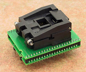
universal adapter, assigned for devices in PLCC44/LCC44. This adapter is
designed for mass-production purposes support also LCC44 packages
operation (mechanical) life of ZIF socket - 10.000 actuations
| Ord. no. |
70-0275 |
| Socket |
ZIF PLCC44, ClamShell type |
| Bottom |
2 rows, 2x22 pins square, 0.6x0.6mm, row spacing 600mil |
| Class |
Universal |
| Subclass |
DIL/PLCC |
|
 |
|
Converter manual
-
Insert converter to the device programmer ZIF
socket according to the picture placed near of it.
If you have some doubts about orientation of this
converter in device programmer ZIF socket, it is
valid general rule, the orientation of the text of
title is the same as the text on the top of the
device programmer.
-
Open the converter ClamShell ZIF socket. Insert
the device into it (place device on contacts). The
right position of the programmed device in converter
ZIF socket is show at picture near (mainly left
above) the converter ZIF socket. On this picture
reference corner (e.g. position of pin 1) of device
is indicated by dot, by number 1, by bezel or by any
combination of them.
-
Visual check interconnection between device and
converter ClamShell ZIF socket. If everything looks
OK, close it and now, device is ready for
programming.
-
Be careful, because the incorrect insertion of
converter to the device programmer ZIF socket or
device to the converter ClamShell ZIF socket can
damage the programmed device.
-
When you finish work with adapter, remove it from
the device programmer ZIF socket.
- To take out the device, open
converter ClamShell ZIF socket and remove device from it.
- When you finish work with
converter, remove it from the programmer ZIF socket.
- Do not directly touch the pins of
the converter and converter ZIF socket, because dirt
may cause errors during programming of device.
- The ZIF socket on the
DIL44/PLCC44 ZIF-CS can accommodate the LCC44
package. A shim must be used to make up the
difference in thickness between the PLCC and LCC
packages. Therefore LCC thickness varies, the shim
thickness will need to be determined for current LCC
device by
Shim thickness = 4,6 mm (0.181
inch) - LCC device thickness
and cut to a
size of 12mm (0.47inch) by 12mm (0.47inch). It
should be affixed to the inside of the cover of the
socket. Test close the socket, without a device, to
confirm the shim does not interfere with the
interlocking parts of the socket.
- Operation conditions: operating temperature 5°C ÷
40°C (41°F ÷ 104°F), operating humidity 20%...80%,
non condensing.
- If programming yields isn't
100% when using programming adapter or if some
unreliability appears, try to connect one 22nF-100nF
multilayer capacitor (that meet the EIA X7R or Z5U
specification) between leads of adapter connected to
pins VCC and GND pins of programmed chip.
- For handling with the device we
recommended to use a
vacuum pick up
tool.
Accepted package(s)
| PLCC44 |
 |
|

|
 Back to top Back to top
The information in this document are subject to
change without notice.
|
