|
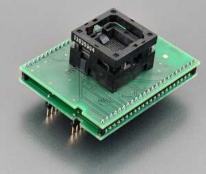
special adapter, assigned for ATMEL ATSAM3X4E devices in BGA144
package
operation (mechanical) life of ZIF socket -
10.000 actuations
| Ord. no. |
70-3029 |
| Socket |
ZIF BGA144, open top type |
| Bottom |
2 rows, 2x24 pins square, 0.6x0.6mm, row spacing 600mil |
| Class |
Specialized |
| Subclass |
ARM |
|
|
|
Converter manual
- Insert converter to the device programmer ZIF
socket according to the picture placed near of it.
If you have some doubts about orientation of this
converter in device programmer ZIF socket, it is
valid general rule, the orientation of the text of
title is the same as the text on the top of the
device programmer.
- Push the top of adapter ZIF socket to open it.
Insert the device into the adapter ZIF socket. The
right position of the programmed device in adapter
ZIF socket is show at picture near (mainly left
above) the adapter ZIF socket. On this picture
reference corner (e.g. position of pin 1) of device
is indicated by dot, by number 1, by bevelled corner
or by any combination of them. Then release adapter
ZIF socket.
- Visually check interconnection between device
and adapter ZIF socket. If everything looks OK, the
device is ready for programming.
- Be careful, because the incorrect insertion of
converter to the device programmer ZIF socket or
device to the converter ZIF socket can
damage the programmed device.
- When you finish work with adapter, remove it from
the device programmer ZIF socket.
- To take out the device, open
converter ZIF socket and remove device from it.
- When you finish work with
converter, remove it from the programmer ZIF socket.
- Do not directly touch the pins of
the converter and converter ZIF socket, because dirt
may cause errors during programming of device.
- Operation conditions: operating temperature 5°C
-
40°C (41°F - 104°F), operating humidity 20%...80%,
non condensing.
- For handling with the device we recommended to use a
vacuum pick up
tool.
Accepted package(s)
| BGA package |
 |
|
|
|
NAME
|
SYMBOL |
MIN |
NOM |
MAX |
|
Profile
|
A |
- |
- |
1.4 |
|
Ball Height
|
A1 |
0.25 |
- |
0.35 |
|
Body Thickness
|
A2 |
0.82 |
0.91 |
1 |
|
Ball Diameter
|
b |
0.35 |
- |
0.45 |
|
Body Size
|
D |
9.95 |
10 |
10.05 |
|
Body Size
|
E |
9.95 |
10 |
10.05 |
|
Ball Pitch
|
e |
- |
0.8 |
- |
|
Ball Array D
|
GD |
- |
12 |
- |
|
Ball Array E
|
GE |
- |
12 |
- |
 Back to top Back to top
The information in this document are subject to
change without notice.
|
