|
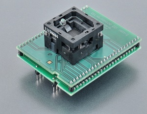
specialized adapter for Atmel ATSAM4S8CA-CU devices in TFBGA100 package
used ZIF socket accepts many variants of supported package, different in ball
diameter, ball high and/or body thickness, see section
Accepted package(s)
operation (mechanical) life of ZIF socket -
10.000 actuations
supported from PG4UW software version 3.11j
| Ord. no. |
70-3350 |
| Socket |
ZIF BGA100, open top type |
| Bottom |
2 rows, 2x24 pins square, 0.6x0.6mm, row spacing 600mil |
| Class |
Specialized |
| Subclass |
ARM |
|
|
|
Converter manual
- Protect the contacts of
adapters's connectors and ZIF socket from
contamination. Any dirt and/or fat on contacts may
cause errors during programming.
- Usage of
vacuum pick up
tool is expected for device handling.
- Proceed with care! Incorrect insertion of
adapter in programmer's ZIF socket or device in
adapter's ZIF socket may lead to programmed device
damage.
- Insert converter to the
device programmer ZIF socket according to the
picture placed near of it. If you have some doubts
about orientation of this converter in device
programmer ZIF socket, it is valid general rule, the
orientation of the text of title is the same as the
text on the top of the device programmer.
- Push the top of adapter ZIF socket to open it.
Insert the device into the adapter ZIF socket. The
right position of the programmed device in adapter
ZIF socket is show at picture near (mainly left
above) the adapter ZIF socket. On this picture
reference corner (e.g. position of pin 1) of device
is indicated by dot, by number 1, by bevelled corner
or by any combination of them. Then release adapter
ZIF socket.
- Visually check interconnection between device
and adapter ZIF socket. If everything looks OK, the
device is ready for programming.
- Be careful, because the incorrect insertion of
converter to the device programmer ZIF socket or
device to the converter ZIF socket can
damage the programmed device.
- The cover must be fully actuated (depressed)
before inserting a device into the socket. If device
is inserted into only partially opened ZIF socket,
then - after releasing of cover - the tweezer
contacts might bend and if repeated several times
this way tweezer contacts might even break.
- Do not press on device while inserting it
and/or releasing the cover.
- When you finish work with adapter, remove it from
the device programmer ZIF socket.
- To take out the device, open
converter ZIF socket and remove device from it.
- When you finish work with
converter, remove it from the programmer ZIF socket.
- Do not directly touch the pins of
the converter and converter ZIF socket, because dirt
may cause errors during programming of device.
- Operation conditions: operating temperature 5°C
-
40°C (41°F - 104°F), operating humidity 20%...80%,
non condensing.
Accepted package(s)
| BGA package |
 |
|
|
|
NAME
|
SYMBOL |
MIN |
NOM |
MAX |
|
Profile
|
A |
- |
- |
1.1 |
|
Ball Height
|
A1 |
0.25 |
0.3 |
0.35 |
|
Body Thickness
|
A2 |
0.67 |
0.71 |
0.75 |
|
Ball Diameter
|
b |
0.35 |
0.4 |
0.45 |
|
Body Size
|
D |
8.95 |
9 |
9.05 |
|
Body Size
|
E |
8.95 |
9 |
9.05 |
|
Ball Pitch
|
e |
- |
0.8 |
- |
|
Ball Array D
|
GD |
- |
10 |
- |
|
Ball Array E
|
GE |
- |
10 |
- |
 Back to top Back to top
The information in this document are subject to
change without notice.
|
