|
|
|
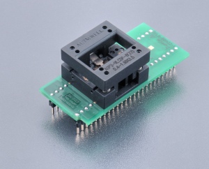
DIL48/BGA22-1 ZIF SFlash-1
Order No.: 70-4392
|
specialized adapter for Serial Flash devices in WLCSP22 package (e.g. Macronix
MX25R6435FxxxL0)
used ZIF socket accepts many variants of
supported package, different in ball diameter, ball high and/or body
thickness, see section Accepted package(s) board
operation (mechanical) life of ZIF socket - 10.000 actuations
supported from PG4UW software version 3.33c
| Ord. no. |
70-4392 |
| Socket |
ZIF BGA22, open top type |
| Bottom |
2 rows, 2x24 pins, square, 0.6x0.6mm,
rows spacing 600mil |
| Class |
Specialized |
| Subclass |
EPROM/Flash |
|
|
|
|
|
Order no.: 70-4392
Price: €
503,00
|
|
Converter manual
- Protect the pins of adapter and adapter's ZIF
socket from contamination. Don't touch the pins with
bare hands. Any dirt and/or fat may cause errors
during programming.
- Usage of
vacuum pick up
tool is expected for device handling.
- Proceed with care! Incorrect insertion of
adapter in programmer's ZIF socket or device in
adapter's ZIF socket may lead to programmed device
damage.
- Insert adapter into
programmer's ZIF socket. If you are in doubts about
orientation of the adapter in programmer's ZIF
socket, there is a rule of thumb - orientation of
adapter's name text is the same as orientation of
the text on the top of programmer.
- Visually check the placement
of adapter in programmer's ZIF socket.
- Push the cover of adapter's
ZIF socket (the topmost movable part) to open the
socket. Once fully actuated, drop the device into
the socket from a height of 2 to 3mm above the
seating plane. For correct device orientation,
follow the instructions shown on picture in PG4UW
software Device info window for device being
programmed. Then release adapter's ZIF socket.
- The cover must be fully actuated (depressed)
before inserting a device into the socket. If device
is inserted into only partially opened ZIF socket,
then - after releasing of cover - the tweezer
contacts might bend and if repeated several times
this way tweezer contacts might even break.
- Do not press on device while inserting it
and/or releasing the cover.
- Visually check the placement
of programmed device in adapter's ZIF socket. If
everything looks OK, the device is ready for
programming.
- To take out the device from adapter, push the
cover of adapter's ZIF socket and remove the device.
- When you finish the work with adapter, remove it
from programmer's ZIF socket.
- Operation conditions: operating temperature 5°C ÷
40°C (41°F ÷ 104°F), operating humidity 20%...80%,
non condensing.
- For handling with the device we
recommended to use a
vacuum pick up
tool.
Accepted package(s)
|
BGA
package
|
 |
|
|
|
NAME
|
SYMBOL |
MIN |
NOM |
MAX |
|
Profile
|
A |
0.335 |
0.365 |
0.395 |
|
Ball Height
|
A1 |
0.14 |
0.165 |
0.19 |
|
Body Thickness
|
A2 |
- |
- |
- |
|
Ball Diameter
|
b |
0.18 |
0.21 |
0.24 |
|
Body Size
|
D |
3.46 |
3.5 |
3.54 |
|
Body Size
|
E |
1.95 |
1.99 |
2.03 |
|
Ball Pitch
|
e |
- |
0.4 |
- |
|
Ball Array D
|
GD |
- |
11 |
- |
|
Ball Array E
|
GE |
- |
5 |
- |
|
|
|
|
|
|
|
 Back to top Back to top
The information in this document are subject to
change without notice.
|
